Appearance
Interface Overview
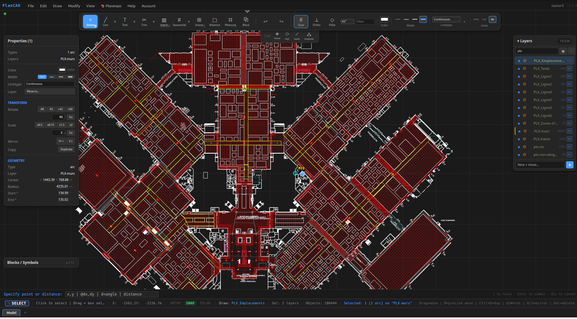
PlanCAD uses a dark, compact workspace designed to keep the drawing canvas as large as possible while keeping all controls accessible. This page describes each area of the interface.
Menu Bar
The menu bar sits at the very top of the window and provides access to every command in PlanCAD organised into menus. It uses zero live subscriptions to the drawing state — menus are built only when you open them — so it never causes performance slowdowns even in large drawings.
File
Handles project lifecycle: New Project, Open, Save (Ctrl+S), Save As (Ctrl+Shift+S), Import DXF/DWG, Export DXF, Export PDF, and Quit.
Edit
Standard editing commands plus several CAD-specific tools:
- Undo / Redo (
Ctrl+Z/Ctrl+Shift+Z) — full undo history across all operations. - Select All (
Ctrl+A), Deselect (Esc). - Delete (
Del), Duplicate (Ctrl+D). - Group (
G) / Ungroup (U) / Explode (E) — group entities so they move and copy as one unit; explode breaks groups or block inserts back into individual entities. - Purge unused layers and blocks — removes layer and block definitions that have no entities referencing them.
- Overkill — removes duplicate and zero-length entities in one pass.
- Select by type / Select by layer — select all entities matching a type or layer across the entire drawing.
- Number stands — batch-assign sequential labels (e.g.
A-01,A-02, ...) to selected entities, sorted by position left-to-right, top-to-bottom. - Number from labels — extract stand numbers from text entities already placed inside stands.
- Service block rules — define rules that auto-generate block instances based on PlanExpo service quantities.
Draw
Activates drawing tools directly from the menu. All tools also have shortcuts listed next to their name. The full set covers: Line, Polyline, Rectangle, Circle, Arc, Ellipse, Spline, Wall (Multiline), Construction Line (XLine), Text, Multiline Text, Dimension, Leader/Annotation, Table, Image, Hatch, and Wipeout.
Modify
Selection-aware editing commands. Many are disabled when nothing is selected:
- Move (
M), Copy (CO), Mirror (MI) — interactive base-point operations on the current selection. - Trim (
Shift+T), Extend (Shift+E), Offset (O), Fillet (Shift+F), Chamfer (Shift+C), Break (B), Stretch (S). - Match Properties (
MA) — copy layer, color, and linetype from one entity to others. - Measure (
X) — measure distances and areas interactively. - Rotate 90° CCW/CW (
Q/W), Mirror Horizontal/Vertical (H/J) — quick one-key transforms on the selection. - Rotate... (
RO) / Scale... (SC) — prompt for an angle or factor, then applies to the selection. - Align (Left, Right, Top, Bottom, Center H, Center V) — align multiple selected entities relative to each other.
- Distribute (Horizontal, Vertical) — space three or more entities evenly.
- Join, Explode, Array (
AR), Fence Selection (FE).
View
- Zoom to Fit (
F) — fits the entire drawing in the viewport. - Zoom to Selection (
Z) — zooms to the bounding box of selected entities. - Zoom Window (
ZW) — drag a rectangle to define the zoom area. - Toggle Snap (
#), Toggle Ortho (F8), Toggle Polar Tracking (F10). - Validate aisle widths — checks minimum clearance between all closed shapes (rectangles and closed polylines) and highlights violations on the canvas.
- Pedestrian flow heatmap — runs a congestion-aware simulation and overlays a color heatmap on the canvas.
- Area summary by layer — calculates the surface area of all closed shapes, grouped by layer.
Help
Keyboard Shortcuts (?) opens a reference sheet of all shortcuts. Check for Updates checks the latest published release and, on the desktop version, can download and install the update automatically. The current version number is shown at the bottom of this menu.
Account
Displays the signed-in email address, the active plan (Trial, Free, or Complete), and the number of trial days remaining if applicable. From here you can Enter license key, Sign out, or upgrade your plan.
PlanExpo
Integration with the PlanExpo stand management platform. Connect to a PlanExpo account, select an event, define an export frame, and push background layers and stand data directly to PlanExpo without leaving PlanCAD.
Toolbar
The toolbar runs vertically along the left edge of the window. It contains all drawing and editing tools, organised into collapsible groups. Each group shows the most recently used tool as the primary button; click the small downward arrow to expand the group and switch to another tool.
Tool Groups
| Group | Primary | Additional tools |
|---|---|---|
| Select | Select (V) | — |
| Draw | Line (L) | Polyline, Rectangle, Circle, Arc, Ellipse, Spline, Wall, XLine |
| Annotate | Text (T) | MText, Dimension, Leader, Table |
| Modify | Trim (Shift+T) | Extend, Offset, Fillet, Chamfer, Break, Stretch, Match Properties |
| Hatch | Hatch (Shift+H) | — |
| Image | Image (I) | — |
| Wipeout | Wipeout | — |
| Stand Number | Stand Number | — |
| Measure | Measure (X) | — |
The active tool button is highlighted in blue. Hovering over any button shows a tooltip with the tool name and keyboard shortcut.
Canvas
The canvas is the central drawing area and takes up the majority of the screen. It is rendered using WebGL for smooth performance even with thousands of entities.
Navigation
| Action | How |
|---|---|
| Pan | Hold Space and drag, or middle-mouse drag, or Shift+drag |
| Zoom | Scroll wheel |
| Zoom to Fit | F |
| Zoom to Selection | Z |
| Zoom Window | ZW, then drag a rectangle |
Snap
PlanCAD's snap engine automatically snaps to endpoints, midpoints, centers, quadrant points, intersections, and grid points. Snap indicators appear on the canvas as small markers when the cursor is near a snap point. Toggle grid snap with # and orthogonal lock with F8.
Grip Editing
When one or more entities are selected, grip handles (small squares) appear at key points: endpoints, midpoints, centers, and vertices. Drag a grip to move that specific point. For polylines, dragging a midpoint grip adds a new vertex.
Selection
- Click to select a single entity.
- Drag left-to-right for a crossing window (selects entities that touch the window).
- Drag right-to-left for a standard window (selects entities fully inside the window).
- Shift+click to add or remove entities from the selection.
- Fence Selection (
FE) — draw a freehand polyline; any entity crossing it is selected.
Copy and Paste
Ctrl+C copies selected entities to the clipboard. Ctrl+V pastes them at an offset of 20 units from the originals. Copy/paste works within a single session.
Layers Panel
The Layers panel appears on the right side of the window, above the Properties panel.
Each layer row shows:
- A color swatch — click to change the layer color.
- The layer name.
- An entity count badge — number of entities on the layer.
- A visibility toggle (eye icon) — hidden layers are not drawn and cannot be selected.
- A selectability toggle (lock icon) — locked layers are drawn but entities on them cannot be selected.
Layer Operations
Right-clicking a layer (or using the context menu icon) exposes additional options:
- Rename — rename the layer in place.
- Set as active — new entities are drawn on this layer.
- Merge into... — move all entities from one or more layers into a target layer and remove the merged layers.
- Delete — removes the layer and all entities on it.
The + Add layer button at the bottom creates a new layer with a generated name, which you can immediately rename.
Tip: Hold Ctrl or Shift in the layers panel to select multiple layers before merging or applying a batch visibility change.
Properties Panel
The Properties panel sits below the Layers panel on the right side. It shows editable attributes for the currently selected entity or entities.
When a single entity is selected, the panel shows:
- Layer — change the layer by choosing from a dropdown.
- Color — per-entity color override. When set to "By layer", the entity uses the layer color.
- Linetype — per-entity linetype override (solid, dashed, dotted, etc.).
- Geometry — numeric fields specific to the entity type. For a rectangle: X, Y origin, Width, Height, and Rotation. For a circle: center X, center Y, and Radius. For a line: start and end coordinates. Click any numeric field to edit it; press
Enteror click away to commit. - Stand number — a custom label field available on all entities, useful for labelling exhibition stands.
When multiple entities of different types are selected, only common properties (layer, color, linetype) are shown.
AI Assistant Panel
A floating, draggable, resizable panel that lets you drive PlanCAD with plain-language instructions. Open it from View > Assistant or via the toolbar toggle. The assistant connects to an AI provider of your choice (OpenAI, Anthropic/Claude, or a compatible service) using your own account, reads your drawing, and makes the changes you ask for — every action stays undoable.
See the dedicated AI Assistant page for setup, what it can do, and privacy considerations.
Command Line
The command line bar sits at the bottom of the canvas, above the status bar. It serves two purposes:
Active Tool Prompt
While a drawing tool is active, the command line shows what the tool expects next:
| Tool | Prompt |
|---|---|
| Line, Polyline | Specify next point |
| Rectangle | Specify corner point |
| Circle | Specify radius or point |
| Arc | Specify point |
| Dimension, Leader | Specify point |
| Text | Specify insertion point |
| Spline | Specify control point |
| Measure | Specify measure point |
| Image | Specify corner point |
Coordinate Input
You can type coordinates directly into the command line instead of clicking on the canvas. Three formats are supported:
- Absolute —
x,ye.g.100,250places the next point at world coordinates (100, 250). - Relative —
@dx,dye.g.@0,3000moves 3000 units upward from the last point. - Polar —
distance<anglee.g.5000<45moves 5000 units at 45 degrees from the last point. - Bare distance — a single number, e.g.
2500, applies the distance along the X axis from the last point.
This is particularly useful when you need to draw to exact dimensions rather than relying on snap alone.
Command Shortcuts
Several commands can be typed directly into the command line field:
FROM— prompts you to click a base point with snap, then enter an offset, allowing you to place entities relative to a known point that is not a snap target itself.AR— opens the rectangular array dialog.ZW— activates zoom window mode.FE— activates fence selection.
Status Bar
The status bar runs across the full width of the window at the very bottom, just above the layout tabs. It is information-only and updates in real time.
From left to right it displays:
- Active tool badge — the current tool name highlighted in blue.
- Contextual hint — a short instruction for the active tool or selection mode, e.g. "Click start point | Distance or next point | Esc = cancel".
- Cursor coordinates — live X and Y position in world units.
- ORTHO — green when orthogonal lock is on, grey when off.
- SNAP — green when grid snap is on, grey when off.
- POLAR — green with angle when polar tracking is on (e.g. "POLAR 45°"), grey when off.
- Draw layer — the name of the active drawing layer, shown in blue.
- Selectable layers — how many layers are currently unlocked for selection.
- Objects — total entity count in the drawing.
- Selected — count and type breakdown of the current selection, e.g. "4 rectangles, 1 line".
When the Measure tool is active, the status bar also shows the accumulated distance, area (if the polyline is closed), and segment count.
Layout Tabs
A row of tabs sits at the very bottom of the window, below the status bar. These tabs correspond to layout spaces in the drawing — similar to model space and paper space tabs in other CAD applications. Click a tab to switch to that layout. Layouts allow you to set up different views of the same drawing data, each with its own viewport and print settings.